Fluid Engineering Laboratory |
Fluid Engineering Laboratory |
AbstractVortical structures of the chain-link-fence type have been experimentally
produced in a plane jet (planar jet, two-dimensional jet or slot jet). The jet was excited by temporal
periodic disturbances with spanwise phase variations
added in the initial shear layer.
Chain-link-fence-like structures, which significantly
differed from ordinary vortices such as "roller and rib" structures,
are observed experimentally by stereoscopic
particle image velocimetry when the temporal phase difference
of disturbances with the spanwise direction being 180 degree.
Some of the original vortices remain downstream as stretched
lambda-type vortices, although the destruction of the orderly vortices
into complex turbulence was significant. |
Manipulation of free shear flow is often accomplished by adding artificial disturbances to the initial shear layer to excite the primary Kelvin?Helmholz(K-H) instability, with the disturbance actually triggering the first roll-up of the shear layer.1,2 In addition to K-H instability, secondary instability such as translative instability,3 which induces a sinusoidal distortion of the spanwise rollers, or braid instability, which generates streamwise vortices such as rib structures,4 can be triggered by adding spanwise nonuniform disturbances.5,6 Lasheras and Choi5 used a fluted splitter plate in their plane mixing layer apparatus to dislocate the origin of the mixing layer periodically in a spanwise direction. Their method was applied to add spanwise periodic streamwise vorticity in the initial stage of the shear layer and form equally spaced rib vortices that connected braids of successive rollers. While their method was passive, Nygaard and Glezer6 established active control of the mixing layer. They placed a linear array of individually controlled surface heaters on the splitter plate, and time harmonic wave trains were introduced into the heaters. If the waves to the adjacent heater segments were out of phase, the spanwise roller and rib vortices exhibited chain-link-fence-like structures.
In the present letter, we observed a structure similar to Nygaard and Glezerüfs, but in a forced plane jet. The initial shear layer of the jet was excited by an array of suction/ blowing miniature jets exiting normal to the streamwise direction of the plane jet. The visualization of the structures was accomplished by a time-resolving stereoscopic particle image velocimetry, and a quasi-three-dimensional vorticity field could be visualized by assuming Taylorüfs frozen hypothesis.
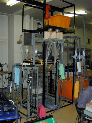
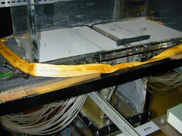
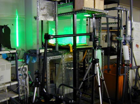
The experiment was conducted in planar water jet apparatus. Water in a reservoir was introduced into a settling chamber having a flow straightener and a mesh. The flow then passed through a smooth contraction nozzle and issued upward into a rectangular Plexiglas tank (640x680x300mm3, in height, width, and span) forming a laminar plane jet with rectangular velocity profile. The nozzle, having a width B=30mm and an aspect ratio equal to 10 at the exit, was designed to add a suction/blowing-type disturbance:it has a row of 60 rectangular slots at the right side (x,y)=(0.33B,0.5B) and the same at the left side (0.33B,-0.5B) aligned in a spanwise direction as illustrated in Fig. 1, which also indicates the coordinate system.
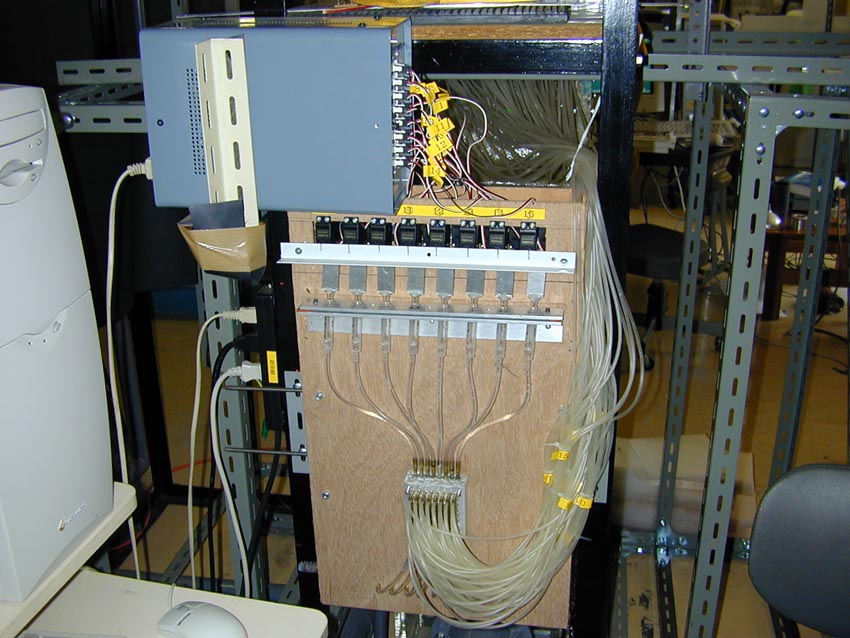
FIG. 1. Details of the nozzle exit. Rows of rectangular slots lead into syringes through plastic tubes and manifolds. Eight sets of syringes, servo motors, and manifolds are used on each side to realize variable spanwise wave lengths.
The cross section of the slot was 1x4 mm2 in height and span, with interval between center of each slot being D=B/6. Each slot lead via plastic tubes to a single manifold, which combined seven or eight other tubes coming from every eighth slot into one. The manifolds were then connected to 1 of 16 glass syringes, each with a capacity of 2 ml. The pistons of the syringes were driven by PC-controlled servo motors (Futaba, S3003). Thus, on both sides were 16 sets of syringes and servomotors, each of which could produce a suction or blowing miniature slot jet. The motion of the piston in the syringe connected to a slot at spanwise location z was determined by a control signal sent to the servomotor expressed as
where XS is the desired position of the piston head measured from the end of the syringe, A is the amplitude of the piston oscillation, Sqr is a square wave with a unit amplitude and 50% duty cycle with phasing like the sine function, f is the amplitude of the phase variation, and c is the phase lag between signals for the shear layer at the left and right sides. The blowing ~suction! slot jet was produced at the rising ~falling! edge of the signal. Typical slot jet velocity vj estimated from a measured position of the piston is shown in Fig. 2. Note that the actual slot jet velocity might not be identical to this figure because the plastic tubes between syringes and slots could be slightly deformed by the oscillating pressure inside.
FIG. 2. Temporal variation of the slot jet velocity estimated from the measured position of the piston in the syringes. Peak velocity of the impulsive slot jet vj is close to the main flow velocity U0 , and its duration was approximately 50 ms.
The spanwise wave length lz of the phase variation was set at lz51.33B. The jet Reynolds number was set at Re5BU0 /n52300, where the jet exit velocity was U0580 mm/s. The jet Strauhal number was set at St 5fB/U050.45 where the frequency f (51/T) was chosento be the most preferred frequency. The corresponding streamwise wave length was lx5U0/2 f51.11B assuming a convection velocity equal to U0/2. The phase lag between shear layers c was set at 0, which created disturbance in both the shear layers in-phase.
Velocity measurement was achieved by the stereoscopic PIV technique, which is capable of resolving time-dependent three-component velocity in a two-dimensional plane. Although the original idea of our custom-made stereoscopic PIV system was based on Ref. 7, we used third-order polynomials as mapping functions between the physical coordinate and the image coordinate, which were obtained by a calibration procedure similar to that described in Ref. 8.
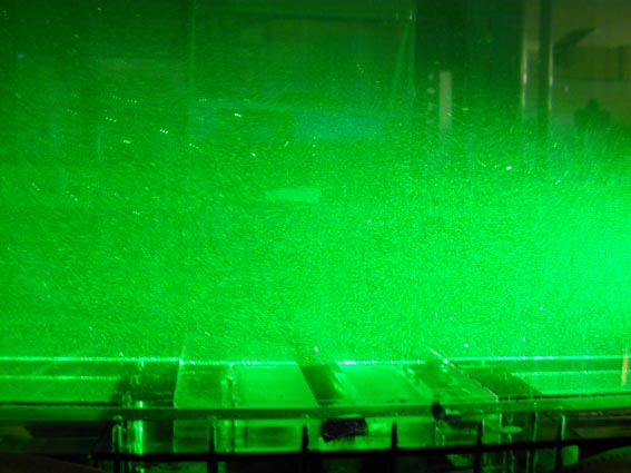
A laser light sheet produced by a Nd-YAG laser ~New Wave Research, MiniLase! illuminated a plane normal to the streamwise direction at x/B52 or 4, and two CCD cameras ~Kodak, ES1.0! were placed to view the same region of interest in the light sheet plane. The angle between the axes of the two cameras was about 90üŗ, and lenses were mounted to satisfy the Scheimpflug condition. The images captured by the CCD cameras were stored into the host memory of a PC through image grabbers ~Imaging Technology, IC/PCI! with a frame rate of 30 fps. Our PIV system could typically capture 150 time-dependent successive images for both cameras. Since an instantaneous velocity field could be measured based on the double images, 75 instantaneous threecomponents velocity maps with 1 15 s intervals were obtained for every run of experiments.
Although our stereo PIV system could resolve velocity distribution only on a two-dimensional plane, the axis normal to the plane was defined as x*52tUC based on the Taylorüfs frozen hypothesis. Here UC is the convection velocity of the structures, approximated as UC50.5UCL , and UCL is a centerline mean velocity of the jet at given x location. Thus the vorticity vector is given as
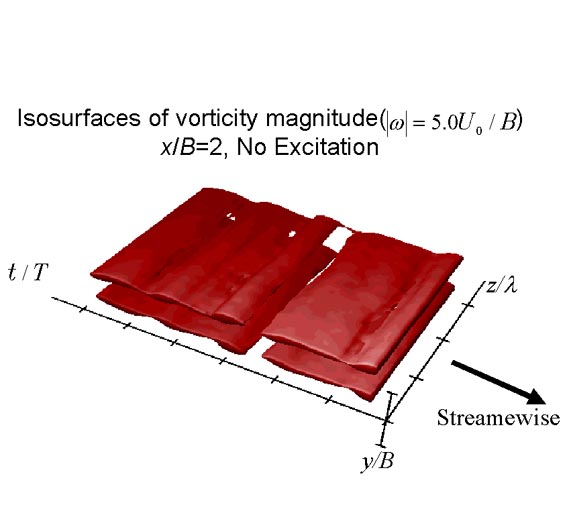
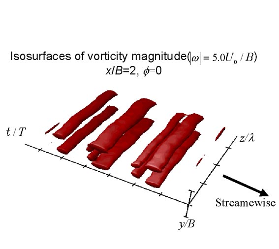
where i, j, k are unit vectors parallel to x, y, and z axes, respectively. The results shown in Fig. 3 represent surfaces of constant vorticity magnitude uvu52.5U0 /B measured in the y2z plane at x/B52. The mean flow direction is provided by an allow in Fig. 3~a!. The structure for f50 in Fig. 3~a! clearly depicts spanwise rollers in each shear layer of the jet. Since the disturbances added to each shear layer were in phase (c50), the rollers are symmetrical in respect to the center plane of the jet. In each shear layer, five rollers are displayed in the figure. Here every two rollers are close to each other and are likely to exhibit vortex pairing further downstream. Since the disturbance was two-dimensional and had no spanwise phase variation, the secondary instability was not triggered explicitly, unlike the following case of f=0. Thus, neither the sinusoidal distortion of the rollers nor the streamwise rib vortices due to the secondary instability are obvious in this stage.
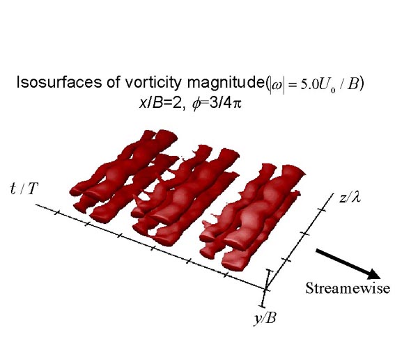
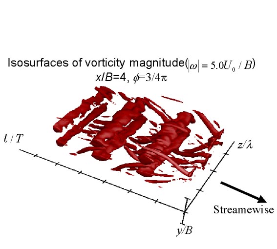
In the case of f=3p/4, the sinusoidal distortion of the rollers is clear, as shown in Fig. 3~b!. The streamwise rib vortices, which are similar to the horns in this picture, are also formed between the adjacent roller pairs.
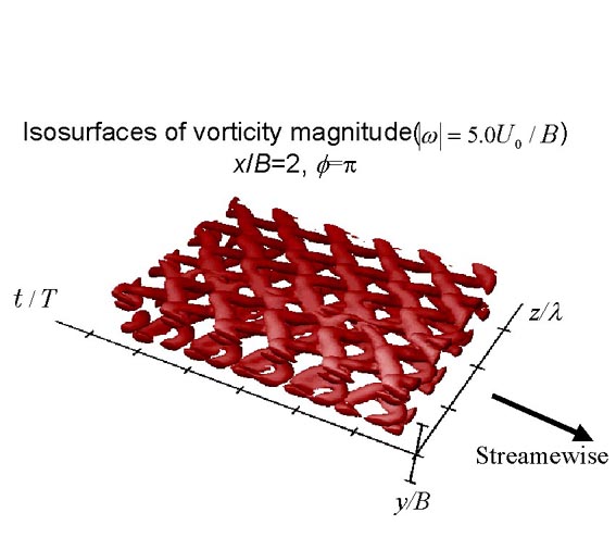
Figure 3~c!, where f5p, exhibits more pronounced features of the structures; it consists of sinusoidal vortices arranged regularly but 180üŗ out of phase between the adjacentone in the streamwise direction. This forms the üeüechain-linkfence- likeüfüf structure described in Ref. 9. The downstream head of the sinusoidal vortex dislocates toward the center plane of the jet, and the tail of neighboring vortex covers it from the outside. These are most likely to be the lambda-type vortices repeated in the spanwise and streamwise directions. Similar structures have been observed experimentally in plane mixing layers by Nygaard and Glezer,6 and simulated numerically by Collis et al.9 The present result is the first observation of such structures in the plane jet.
Nygaard and Glezer6 observed that the chain-link-fence pattern was not formed if the wave angle is greater than a cutoff angle of approximately 45üŗ. By Collis et al.,9 on the other hand, the cutoff angle of the experiments by Nygaard and Glezer6 was estimated as 56üŗ according to linear stability analysis. Since the wave angle of the present case ~40üŗ! was relatively smaller than the above criterion, the chain-linkfence pattern was expected to appear. Note that we did not observe the chain-link-fence pattern in the case of lz50.67B, which is half the wavelength above.
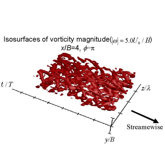
Further downstream, x/B54, the chain-link-fence structures were broken into turbulence and exhibited more a complicated vorticity field, as shown in Fig. 4. However, the lambda-type vortices were still observed in some part of the flow. They were further stretched toward the streamwise and transverse direction.
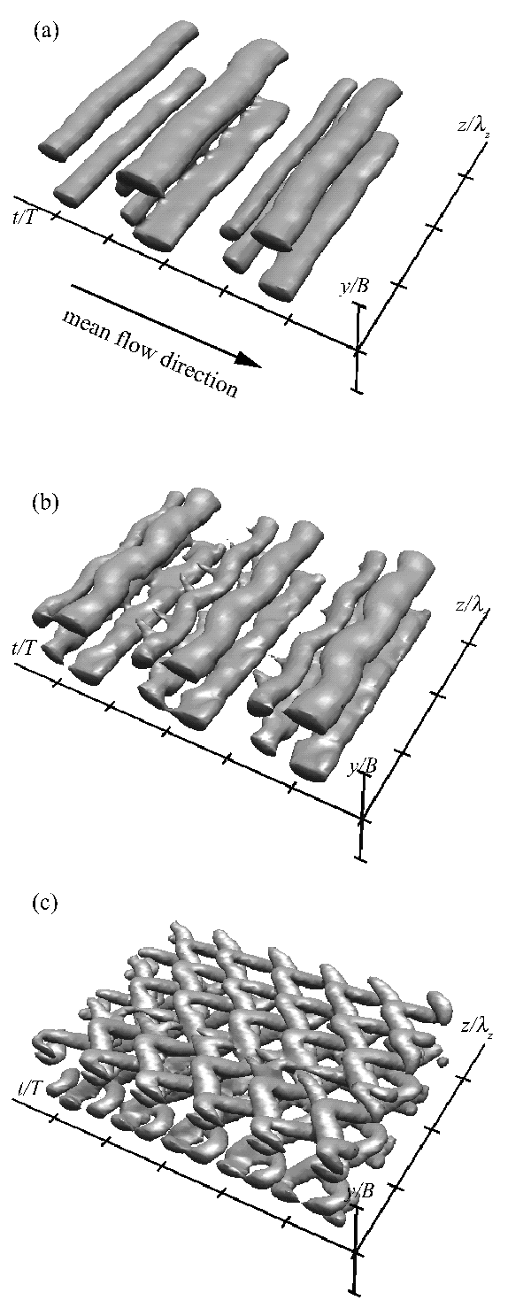
FIG. 3. Surfaces of constant vorticity magnitude threshold at uvu52.5U0 /B calculated from the time-dependent PIV data measured at x/B=2; (a) f=0, (b)f=3pi/4, (c) f=pi. Tic intervals are respectively 1.0T, 1.0B, and 1.0lz in t-, y-, and z-directions.
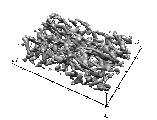
FIG. 4. Surfaces of constant vorticity magnitude threshold at |omega|=2.5U0 /B calculated from the timedependent PIV data measured at x/B=4 for the case f=pi. Tic intervals are the same as those of Fig. 3.
This work was supported by a grant-in-aid for scientific research by the Ministry of Education of Japan under Grant No. 10750140.
1 C. M. Ho and L. S. Huang,"Subharmonics and vortex merging in mixing
layers," J. Fluid Mech. 119, 443 ~1982!.
2 D. Oster and I. Wygnanski, "The forced mixing layer between parallel
streams," J. Fluid Mech. 123, 91 ~1982!.
3 R. T. Pierrehumbert and S. E. Widnall,"The two- and three-dimensional
instability of a spatially periodic shear layer" J. Fluid Mech. 114, 59
~1982!.
4 S. J. Lin and G. M. Corcos, "The mixing layer: Deterministic models of a
turbulent flow. Part 3. The effect of plane strain on the dynamics of
streamwise vortices" J. Fluid Mech. 141, 139 ~1984!.
5 J. S. Lasheras and H. Choi, "Three-dimensional instability of a plane free
shear layer: An experimental study of the formation and evolution of
streamwise vortices," J. Fluid Mech. 189, 53 ~1988!.
6 K. J. Nygaard and A. Glezer, "Core instability of the spanwise vortices in
a plane mixing layer," Phys. Fluids A 2, 461 ~1990!.
7 A. K. Prasad and R. J. Adrian, "Stereoscopic particle image velocimetry
applied to liquid flows," Exp. Fluids 15, 49 ~1993!.
8 S. M. Soloff, R. J. Adrian, and Z. C. Liu, "Distortion compensation
for generalized stereoscopic particle image velocimetry,"Meas. Sci.
Technol. 8, 1441 ~1997!.
9 S. S. Collis, S. K. Lele, R. D. Moser, and M. M. Rogers, "The evolution
of a plane mixing layer with spanwise nonuniform forcing,"Phys. Fluids
6, 381 ~1994!.