Research and Development in Mechanism, Conrol
and System Engineering Laboratory
This page introduces only those research
presentations made at academic conferences.
We have reported at the Japan Society for
Design Engineering Spring and Autumn Conference
Research Lectures, the Robotics Society of
Japan Academic Conference, and the Japan
Society of Mechanical Engineers Robotics
and Mechatronics Conference, among others.
Older examples are listed at the top, but
if you look at the older years, you will
see that there are themes where improvements
are being made little by little and are continuing.
As the research presented at academic conferences
is publicly known, only the names of the
researchers (conference presenters) are listed.
2014
Our laboratory was established in 2011.
As you know, 2011 was the year of the Great
East Japan Earthquake, so the start of spring
semester classes was delayed by about a month,
and with the launch of the laboratory, it
was only thanks to the hard work of the original
members that we were finally able to present
our results at an academic conference.
Graduate students who graduated in 2013 (March
2014) worked so hard that, as our university
had just completed a new campus building
in Nakano, we were able to report our results
at the conference held there.
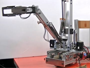
7-degree-of-freedom robot arm with gravity
compensation function
|
Robots require powerful actuators (motors,
etc.), but compared to muscles, motors are
heavy and have insufficient power (torque).
(Muscles have about 10 times the output of
motors with the same mass. This is evaluated
as the output-to-weight ratio.) Therefore,
there is a problem that the limited power
(torque) is wasted just by supporting the
robot's own weight. Therefore, if the weight
of the arm is left to a spring, the motor
can be used for the intended movement. A
mechanism that balances the arm in a changed
position is called a gravity compensation
mechanism, and we thought of incorporating
this into a robot arm. For safety reasons,
it is better to keep the motor output low
when using a robot near a human, so this
principle is effective. In addition, the
joint arrangement of an arm that is close
to a human has seven joints, so the main
purpose of this research is to make a design
effort to apply the gravity compensation
principle to this joint configuration. A
larger number of joints allows for a wider
variety of postures to be selected, but we
believe that a more human-like posture for
the arm not only increases compatibility,
but also makes the robot's movements easier
to predict for nearby humans, making it safer.
モータ:コマンド型サーボモータ
関節自由度:7
|
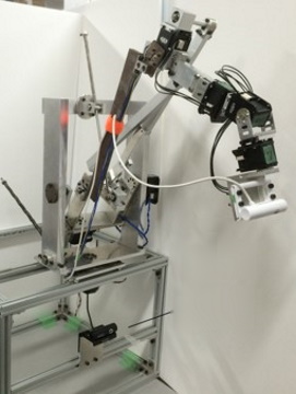 |
| 担当者:横山(2013年度 修了) |
2015
Master's student who graduated in 2014 made
sudden progress in the content of thier master's
thesis, producing good results, so the laboratory
announced this.
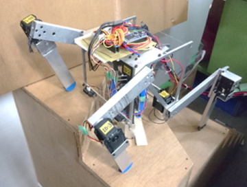
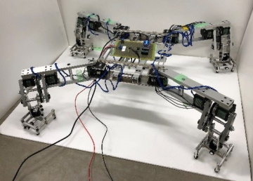
4+1 legged walking robot capable of ascending
and descending surrounding stairs
Circular stairs are often seen in homes and
facilities, but they are difficult
for legged
robots. They save space in building
design,
and for humans, they have the advantage
that
if they step off, they will stop at
the circular
stairs, so it is hard to imagine them
going
away. For wheeled or crawler-type robots,
the slope is different on the inside
and
outside, and there are continuous steps,
so it is difficult to move around.
We thought
that legged robots would be suitable
for
such places, and initially considered
a four-legged
robot. By switching feet, it can turn
on
the spot, but in the case of a moving
surface
with a spiral slope such as a circular
staircase,
the front legs are bent, so there is
a high
possibility that the knees will come
into
contact with the wall, and we found
that
we needed to devise a control strategy
for
this. Therefore, we devised a machine
with
additional legs that only extend up
and down
and turn at the bottom center of the
body.
On a circular staircase, after climbing
on
all four legs, the additional legs
are extended
to support it, and the four legs are
folded
and turned, and this is repeated. This
robot
is characterized by its simplified
operation
sequence.
モータ:コマンド型サーボモータ
関節自由度:10(1脚あたり2関節×4,中央支持脚2自由度)
|
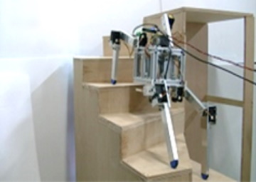 |
| 担当者 笠井(2014年度 修了) |
2016
Master's studenst who graduated in 2015 suddenly
improved the content of thier master's thesis,
producing good results, so the laboratory
announced this.
4+1 legged walking robot (modified) capable
of ascending and descending surrounding stairs
| It has long been argued that legged robots
are generally inefficient in energy efficiency.
The reason for this is that power must be
supplied to the motors in order to support
their own weight. The solution is to provide
a mechanism that does not consume energy
when supporting its own weight, and a mechanism
has been added that can lock when the central
support leg is supporting and stopped. A
major feature of this robot is that it does
not add an additional motor for locking,
but rather uses the coordinated movement
of the motors for extending and retracting
the legs up and down. The only sensor used
is a proximity sensor, but this alone is
enough to recognize stairs, and the robot
was able to traverse a straight-bend-straight
staircase. Reliable movement is achieved
by including actions in the walking sequence
to compensate for the characteristics of
the proximity sensor. |
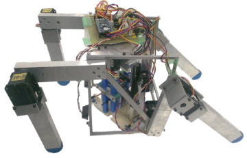 |
| 担当者 村尾(2016年度 修了) |
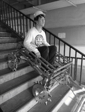
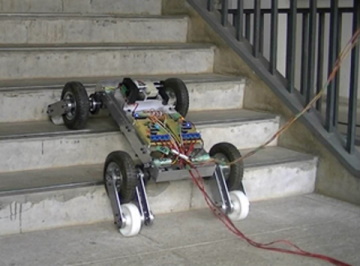
A wheeled and extendable vehicle robot that
can climb stairs
When talking about robots that climb stairs,
the most familiar type is the rubber
crawler
type used for transporting luggage.
Crawlers
are used in construction machinery,
and it
is obvious that they can run on rough
ground,
but they are suitable for irregular,
soft,
and slightly rough surfaces, which
is why
we think they are suitable. <BR> Indoor
stairs are hard and have a regular
shape,
and of course we want to avoid moving
around
by rubbing, so we thought that crawlers
might
not be the best option. <BR> When
dealing with heavy objects, we have
an option
other than legs, so we use wheels,
but in
order to grip the steps and climb them
reliably
by using the shape rather than friction,
we added protrusions to the outer circumference
of the wheels. These protrusions are
movable
and slide into the steps, and after
they
touch down, the claws bite into them,
allowing
for reliable operation. The height
of the
steps varies, but the unique feature
of this
robot is that it is designed to passively
adapt to general stairs.It is very
slow,
taking 2-3 minutes to climb one floor,
but
it is now possible to move steadily
and reliably.
Building 4 has only stairs, so it is
difficult
to carry heavy objects (such as machine
tools)
up the stairs. One time, two people
tried
to carry a small milling machine up
the stairs,
but it was so heavy that they had a
very
hard time*. They gave up after the
first
or second floor, so they asked for
help and
managed to carry it up the second and
third
floors with four people. This experience
was the inspiration for this research.
モータ:DCモータ×4
制御:速度比例制御
段鼻間適応:原付用スプリング&ダンパー
※業務・実務上は持ち上げて良い重量が限られています.重量物を運ぶ特殊な技能を持っていない限り,極度に重いものを運んではいけないと考える必要があります. |
 |
掲載論文
加藤恵輔, 中村祐介, 長谷川一樹, 根崎雄太, "移動支援と運搬作業支援を行う階段昇降移動ロボットの設計・開発", 設計工学, 55.2(2020),117-128.
担当者 中村(2014年度 修了),長谷川(2015年度 修了),根崎(2018年度 修了) |
Vehicle robot with revolutionary wheels that
can climb up and down steps
Wheeled carts such as luggage carts have
difficulty getting over steps of around 20mm*,
so moving over steps is a challenge for wheels.
Legs are good at moving over steps, but the
control is complex, they consume a lot of
energy, and many motors are needed (at least
12 for four legs), so we thought about whether
we could solve this problem with wheels as
much as possible. We could make a combination
of wheels and legs, but to avoid increasing
the number of motors more than necessary,
we devised a method of adding only one degree
of freedom per wheel and attaching small
wheels to the ends of the legs so that they
move just like revolving around the main
wheels. The main wheels and the revolving
wheels are linked, and are driven by a belt
so that the peripheral speed (tangential
direction) is equal. It is equipped with
a distance sensor that detects steps, and
when it approaches a step, it revolves the
revolving wheels, which hook onto the step
and climb up the step. If a step is detected,
it can ascend and descend using sequence
control (predetermined actions). When we
exhibited this robot at an exhibition, a
person in a wheelchair with paralysis of
the legs told us that he would like to see
it put to practical use.
モータ:DCギヤードモータ×8
制御:車輪角速度制御,公転アーム角度制御
センサ:段エッジ検出用距離センサ
※道路の縁石の低くなったところはこの値までと決められていますが,台車,ベビーカー,歩行支援のカート,電動車椅子の前輪など不安定な挙動を目にしたことがあるかと思います.あの段差でも車輪にとっては問題があると考えています. |
 |
| 担当者 長岡(2015年度 修了),平松(2017年度 修了),石塚(2018年度 修了) |
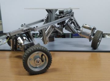
Vehicle-type robot that can handle single-sided
slopes
When a mobile robot climbs a steep slope,
it is necessary to consider the characteristics
of the terrain, such as the inclination,
as well as the fragility of the surface to
be moved. It is also important that the robot
can stop halfway before reaching the top.
Therefore, while some mobile robots based
on high power and inertial force have considerable
performance in terms of climbing up a slope,
it is generally difficult for them to stop
reliably halfway up a slope. Legged robots
are suitable for moving freely on slopes,
and if the legs can be designed to prevent
sinking into the fragile ground, they can
move freely. The advantage of crawlers is
the large contact area, which allows them
to move reliably, but they may not be good
at moving off the slope. In the case of wheels,
as mentioned above, they may be able to run
through it by relying on inertia, but in
order to stop halfway or to climb slowly
and reliably, the wheels must be designed
in a way. Nevertheless, the advantage of
wheeled robots is their simplicity, and this
research is an attempt to see if this can
be utilized. To move freely on slopes, it
is necessary not only to have the so-called
climbing ability, but also to be able to
move in one direction of the slope (in the
direction of the contour lines), and if this
is possible, it will be possible to move
quite stably. We designed the suspension
to ensure lateral stability, and rather than
having a roll center like an automobile,
each wheel is designed to tilt based on a
center of rotation that is further outward
than the body of the vehicle. The wheels
are positioned so that they are pushing against
the valley side, so we came up with a mechanism
that makes it less likely to tip over. In
fact, the idea came from the way you use
your uphill and downhill feet (outside and
inside feet) when skiing (although pushing
against the outside is not a good action
when skiing), and it was also inspired by
an idea from a fairly old concept car that
improved cornering performance by changing
the position of the wheels relative to the
ground.
モータ:DCギヤードモータ×5
制御:車輪角速度制御,傾斜適応角度制御
センサ:2軸加速度センサ(傾斜検出用) |
 |
掲載論文
加藤恵輔, 吉尾一平, 相田利博, "傾斜適応して片斜面走行可能な車輪型不整地移動ロボットの研究", 設計工学, 55.10(2020), 629-644.
担当者 吉尾(2015年度 修了),相田(2017年度 卒業)
日本設計工学会 2020年度 論文賞受賞 |
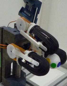
3-fingered hand with a winding mechanism
that realizes a pick-up function
| Research on robotic hands is old, and has
been developed since the early days of robotics.
It is a field that is actively tackled by
researchers in the fields of robotics, control,
and intelligence, and is still being researched
today. With the advancement of image processing
technology, it is possible to move the fingers
according to the shape, position, and posture
of the object, but this is surprisingly difficult.
Of course, it can be said to be easy with
advanced technology, but it cannot be denied
that the system is rather exaggerated compared
to the simple action of picking up, so we
thought about how to make it easier. There
are ideas such as using negative pressure
to adhere, but we thought that using a servo
motor would be easier to grasp the condition
of the finger angle and easy to control.
By the way, have you ever felt that it is
difficult to pick up small objects or paper
when your fingers are dry and dry? At this
time, we thought it would be easy if we could
make a pulling motion, so we came up with
a method of attaching a belt to the fingertip
and pulling in the object like a conveyor
and picking it up. All you have to do is
pinch the object with the right amount of
force according to its size and turn the
belt, so there is no need for complicated
control. For example, if you press lightly
against something like cloth, it will wrap
around it, making the movement very easy.
The human hand is well-made, but it uses
many muscles and tendons and has a good degree
of freedom in the joints. The muscles themselves
have excellent characteristics and a finely
distributed sensory system, which is extremely
difficult to perfectly reproduce, so we think
it may be effective to achieve a grasping
function with a completely different structure. |
 |
| 担当者 山森(2014年度 卒業),鈴木(2012年度 卒業) |
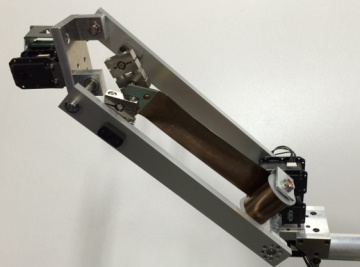
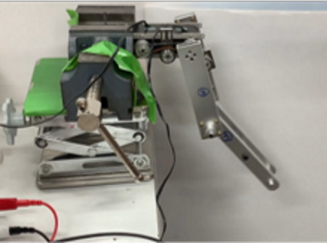
Robot arm with gravity compensation mechanism
using a constant force spring
| As you know, a spring's force increases in
proportion to its displacement, but it does
not provide a very large stroke. On the other
hand, there is a spring like a power spring
that can provide a large stroke; this is
called a constant force spring. This research
was started to see if constant force springs
could be used in gravity compensation mechanisms.
In the case of an arm, the amount of compensation
that needs to be done changes depending on
the posture, so it is necessary to come up
with a mechanism that takes this into account.
At the time, it was not possible to find
a way to provide complete compensation using
a constant force spring, but with some ingenuity
(adjustments) in the design, it was possible
to achieve compensation with a small amount
of error. In the photo, the band-like thing
between the links is a constant force spring. |
 |
| 担当者 細野(2017年度 修了),三浦(2013年度 修了) |
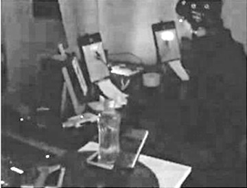
Control of a robot arm using visual evoked
potentials
| There is a phenomenon where the flicker of
light that enters the eye modulates brain
waves. For example, when the brain waves
seen when looking at a light flashing at
10 Hz are subjected to a Fourier transform,
a 10 Hz signal is obtained. This phenomenon
is called the visual evoked potential, and
it can be used to make a robot move simply
by looking at a flashing light source. This
idea was given to us by the Health and Medical
Engineering Laboratory on campus, and we
used this as a basis to consider whether
it could be incorporated into a robot. However,
the range of recognizable frequencies is
limited, and considering the modulation of
brain waves and the time required for the
Fourier transform, it cannot be said that
it can handle a large number of types of
commands. Therefore, by increasing the number
of commands with a hierarchical user interface
and assigning a control sequence to each,
we created a user interface that allows users
to select actions rather than control them,
and move the robot arm. |
 |
| 担当者 小坂(2014年度 修了) |
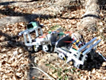
Articulated mechanism and vehicle robot adaptable
to uneven terrain
| When a wheeled robot runs on uneven ground,
the driving force is not transmitted when
the wheels hit an uneven surface, and the
robot cannot move. However, by connecting
the two vehicles, the advantage is that the
driving force of the vehicle with better
ground contact can be utilized. In the world
of robots, snake-shaped robots were developed
a long time ago, but the potential of multi-jointed
robots is great, and we thought that even
vehicles connected together might be effective.
The way in which the force is transmitted
when connected is important, and if a simple
connection is used, when the ground contact
of the front part becomes poor, the force
pushing from behind can cause the robot to
lose its posture, changing its posture in
an unexpected direction and preventing it
from running as intended. Therefore, when
two vehicles are in a bent posture, we thought
it would be better to push in the direction
that would return them to a straight posture,
and considered using cross links in the connecting
mechanism. By using this mechanism principle,
for example, when turning left, the point
of action shifts from the center to the left,
so we can expect the effect of making it
less likely to lose its posture even if it
is pushed hard from behind. Although there
are still issues with the pitch direction
(forward and backward tilt), the simple vehicle
is able to navigate the uneven ground on
campus and adapt to uneven surfaces such
as tree roots. |
 |
| 担当者 小林(2015年度 修了) |
2017
4+1 legged walking robot capable of ascending
and descending surrounding stairs (improvement
and function expansion)
| We have adjusted the ratio of the thigh and
shin lengths of the front and rear legs for
a robot we have already proposed. At first
glance, this may seem like a minor change,
but it has had the effect of expanding the
range of motion of the toes on spiral staircases
and avoiding joint angles that put a strain
on the motor (longer moment arms relative
to the robot's own weight). In robot development,
optimizing designs to suit specific purposes
is also an important technology. <BR> Also,
in order to increase the contact polygon
of the foot of the central supporting leg
and improve stability, a mechanism has been
added to the spiral staircase section that
transforms from a square into a long, thin
trapezoid. No motor is used for this transformation,
and it transforms passively, with the added
ability to lock when a grounding force is
applied. |
 |
| 担当者 笠井(2014年度 修了),村尾(2017年度 修了) |
階段昇降可能な公転車輪を有する伸縮型車輌ロボット(改良・機能拡充)
提案・試作した装置で,段差を登れるようになりましたが,[段差昇降可能な公転車輪を有する車輛ロボット]では段が登れるので,試しに胴体部に伸縮機能を付けたら階段を登れるのではないかと考えて開発したものです.
開発のきっかけは単純でしたが,思いの外,安定した階段昇降動作を実現することができました.伸縮式胴体は単に階段の間隔に合わせるためのものだけでなく,前後いずれかの車輪が止まっているため,安定した状態を作ることができ,簡潔な動作制御で階段を昇降できるのです.
階段は,踏面(ふみづら:水平方向)と蹴上(けあげ:高さ方向)から成りますが,登りでは蹴上への接触,下りでは踏面への接触を検知できれば,容易に動作可能という,簡単な動作が実現しました. |
 |
掲載論文
加藤恵輔, 平松大生, 長岡秀磨, 石塚岳, "自公転車輪と伸縮型車体を用いた段差・階段移動ロボットの開発
(機構設計と階段昇降実験)". 設計工学, 55,4(2020), 253-262.
担当者 長岡(2015年度 修了),平松(2016年度 修了),石塚(2018年度 修了) |
2018
Sensing and control of a 4+1 legged walking
robot capable of ascending and descending
a circular staircase (control method study)
The greatest achievement is that it is now
possible to walk using only simple sensors.
On the spiral staircase, it is necessary
to accurately determine the path so that
it is perpendicular to the bisector of the
triangular section, and the surface of the
riser must be detected. We attempted to use
inexpensive infrared reflective distance
sensors, and selected a system that uses
two pairs, one on the left and one on the
right. As the change in output voltage is
small under certain conditions (distance),
we devised a mechanism that intentionally
rotates the robot in a swaying motion to
create a state of good sensitivity. With
these improvements, we have completed the
entire series of developments. The evolution
of this research is as follows:
- Timing belt and telescopic mechanism are
used for central leg extension and retraction
- The leg link length has been fine-tuned,
the aircraft frame has been made lighter,
a rack and pinion is used to extend and retract
the central leg, and a mechanism is installed
that latches under its own weight.
- Added a measurement operation that compensates
for the resolution of the infrared short-distance
sensor. Can safely pass through straight
and circular stairs.
- An intermediate telescopic leg mechanism
has been added to ensure sufficient support
polygon even in the surrounding staircase
section.
The following year, in an attempt to further
reduce the degrees of freedom, we eliminated
the extension and retraction degrees of freedom
from the central support leg and changed
it to only rotational degrees of freedom,
but it became difficult to achieve the desired
movements, so we concluded this research
with the results achieved up to 2018.
Therefore, in this research, we believe
that
a two-degree-of-freedom mechanism for
the
four legs, and one with Z-axis extension
and yaw-axis rotation for the lower
trunk
would be suitable. |
|
掲載論文
加藤恵輔, 村尾彰太, 笠井航, "屋内回り階段を昇降可能な中心支持脚を有した
4 脚ロボットの開発 (中心支持脚の駆動系と足機構の設計)",
設計工学, 55, 3(2020), 177-190.
担当者 笠井(2014年度 修了),村尾(2017年度 修了) |
Improved four-fingered hand with a winding
mechanism that realizes picking up function
| A flat belt was used for the winding belt,
and while this was effective in certain directions
and with certain shapes, it was often impossible
to obtain a stable contact state. We therefore
modified the design by making the fingertips
spherical, so that although it was point
contact, it would always make contact, and
to achieve this we devised a structure that
arranged round belts. Furthermore, we provided
an axis so that the sphere could rotate on
a certain axis, and designed it so that grooves
of different radii were arranged around the
axis to create a spherical surface. We also
gave the finger a manipulation function that
allows it to rotate objects held in the hand
by rotating it in a twisting direction. |
 |
| 担当者 木幡(2017年度 修了) |
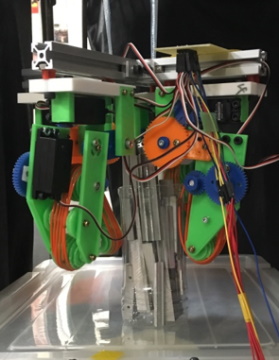
Robot arm with variable gravity compensation
mechanism using non-circular pulleys and
interference drive
| In order to advance the design theory of
gravity compensation mechanisms that use
constant force springs, we devised a way
to obtain accurate compensation torque, but
some error remained. To resolve this, we
used a pulley made by precisely calculating
the amount of compensation, and a drive system
that uses the principle of interference drive,
in which multiple motor torques work together
effectively. This prototype focuses on the
fact that original products can be made using
CNC machining machines, without using general-purpose
products. This is mainly a research project
to propose the principle, but if successful,
it may be possible to apply it to use next
to humans or when worn by humans. As shown
in the right figure, the pulley was made
based on the obtained shape data, which is
a distinctive feature. As CNC milling machines
have become easier to use, it is possible
to make shapes like this as long as tolerances
are allowed within a certain range, making
it possible to try out new functions. |
キーデバイスの非円形プーリ |
| 担当者 篠本(2018年度 修了) |
2019
Foot mechanism for a quadruped walking robot
with terrain adaptability
| In recent years, legged robots with dynamic
movements backed by advanced control have
become mainstream, and simple sole mechanisms
are sufficient. However, depending on the
operating environment, such as inside a home,
there are cases where you do not want to
increase the contact pressure, and when slow
and reliable movements are required, static
movements are used. In such cases, it is
necessary to ensure the support moment of
the foot. It is important not only to make
the sole of the foot large, but also to be
able to generate sufficient contact reaction
force even on the outside. Even the slightest
unevenness can cause the robot to wobble,
and soft soles can cause it to stumble, so
a device is required that receives the contact
reaction force equally on all parts that
come into contact with the ground. If the
foot mechanism can make reliable contact
with the ground, it will be easier to control
a walking robot, and if a basic gait (way
of moving the feet) can be generated, the
burden of posture control can be reduced
and flexible control will be possible. This
idea is a simple mechanism, and I had been
thinking about it since the end of the 20th
century, but I had not had the opportunity
to realize it and had left it lying around,
so I suddenly realized it. |
 |
| 担当者 傅(2020年度 修了) |
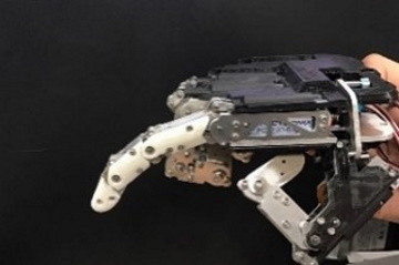
Low-degree-of-freedom multi-joint drive active
prosthetic hand
| Research into using motors to power prosthetic
arms and legs has a long history, and although
a wide variety of prosthetics have been created,
they have not yet become widespread, remaining
mainly decorative prosthetics that are natural
in shape but cannot move. In addition to
their high cost, a major issue is the need
to become accustomed to operating them using
electromyography and electroencephalograms.
This research considered that operation could
be simplified by devising a structure that
could move many joints with a small number
of motors by devising a degree of freedom
(number of motors, number of joints), and
also investigated a design method that could
create a skeletal structure by cutting out
material of a certain thickness and combining
it. Basically, it can only open and close,
but if used in a creative way, it has the
unique feature that it can be used not only
for grasping, but also to perform several
everyday movements by combining it with the
healthy hand. |
 |
| 担当者 吉田(2021年度 修了) |
Robot arm with variable gravity compensation
mechanism using non-circular pulleys and
interference drive
| If we knew the weight of the object being
held, rather than just its own weight, we
could compensate for that amount and allow
for even more freedom in movement. For this
reason, we devised and developed a mechanism
that can adjust the amount of compensation
in the gravity compensation mechanism. This
arm has a drive system that combines a gravity
compensation mechanism with an interference
drive to make up for motor torque, which
tends to be insufficient. Of course, power
will be used to make the adjustments required
for compensation, but this can be adjusted
in a few seconds, and once this has been
compensated for and locked, the motor will
only consume power for acceleration and deceleration,
i.e., for inertia, so the longer the operation
time, the less power is wasted, and so we
believe there is value in making the gravity
compensation mechanism variable. |
 |
| 担当者 篠本(2018年度 修了) 近藤(2017年度 修了) |
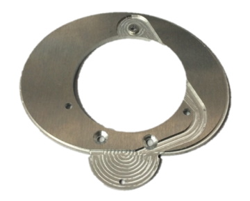
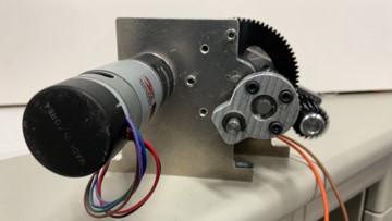
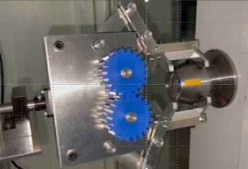
Reduction mechanism that achieves a large
reduction ratio by using a planetary gear
mechanism and a difference in the number
of teeth on an internal gear
| In the world of robotics, there are wonderful
reduction mechanisms known as harmonic drives
and RVs that provide a large reduction ratio
and have almost no backlash. These are expensive,
but depending on the purpose, they are still
worthwhile. However, they are not something
that can be used casually, as there is a
high risk of them breaking if their usage
and specifications are not carefully considered
and they are not operated in a well-managed
manner. This device was developed out of
a desire to develop a simple mechanical element
that has a large reduction ratio, relatively
little backlash, and is made up of sturdy
or easily available parts. The principle
is that if two internal gears with different
numbers of teeth are used and another gear
is meshed with them at the same time and
rolled, a relative rotation will be generated
between the two internal gears. This principle
is similar to harmonic drives, but what sets
them apart is that they are made up of normal
gears. |
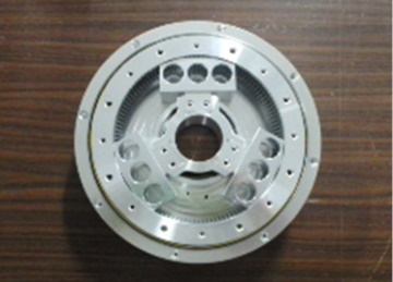 |
登録特許
発明の名称:減速装置
発明者 :加藤恵輔、菊池快
出願人 :学校法人明治大学
整理番号 :2014−P21
登録番号 :第6418689号
登録日 :2018年10月19日
担当者 菊池(2016年度 修了) |
Remote control system with separate hand
and arm wrist positions
| So far, we have made robotic arms, and we
have been considering ways to remotely control
them. Measuring force and feeding it back
to the control system is an effective method,
but we wondered if there was an easier way
to do this, and so we developed an control
system that separates the hand and arm movements
and assigns them to the left and right hands.
We have found this to be unexpectedly easy
to operate. The hand position is properly
aligned and then the hand is closed, and
by separating this process, there is no frustration
that the hand moves when closing the hand,
and reliable operation is possible. We have
exhibited it at exhibitions attended by people
from elementary school students to the general
public, and have allowed them to actually
touch and operate it, and we believe that
the system is effective because it is easy
to operate without any special explanation. |
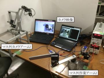 |
| 担当者 細野(2017年度 修了),篠本(2018年度 修了),横山(2013年度 修了) |
プロペラを用いた脚式ロボットの安定可制御系
| 有志学生らで,面白いロボットを作ろうと考えたものです.ドローンに興味があり,脚式ロボットに興味があり,マイコンでの制御に興味があり,といった背景から,脚式ロボットの姿勢制御にドローンを使ったらよいのではないかと考えたものです.4脚ロボットは通常,体幹姿勢を保ち,対地速度も一定いることから,多軸ジャイロと多軸加速度センサを組み合わせ,傾きを検出したらプロペラを回して姿勢制御します.脚式ロボットは歩容生成のみ行い,姿勢制御はプロペラで行います.脚の関節も最低限の数ですが,きちんと歩くことができました. |
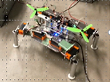 |
| 担当者 傅(2020年度 修了) 藤野(2019年度 修了) |
円筒座標配置の脚機構を有した4脚ロボットおよび足先車輪による滑走動作制御
| 簡単に歩け,これまでにない4脚ロボットを作ろうという目標から開発されたロボットです.ローラースケートの後退動作はちょうど蛇のくねり動作同様で,これを模したロボットは20世紀のうちに開発されていますので,全く異なる方式でできないかと考えたものです.4脚ロボットは脚構成を変えるだけで難易度が変わりますが,本機体では,脚の根元の関節を中心に合わせ,円筒座標系のように4脚を配置したものとなっています.意外とあるようでない構成で,各足に固定型車輪を付け,独自の歩容を開発しています. |
 |
| 担当者 傅(2020年度 修了) |
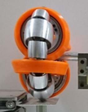
段差乗り上げを実現するオムニホイル型車輪機構
全方向移動車輛を構成するのに一般的となったオムニホイルですが,扱いの手軽さとは裏腹に段差を乗り越えにくいという弱点があります.周方向に配置された樽型の受動小車輪の直径が小さいことが原因です.これを大きくするにも限度があり,3つ並べるのが限度であるため,車輪直径に対して1/3程度までとなります.そこで,この車輪を大きくするための配置を検討した結果,複数の直径の小車輪を用意し,互いに入り込むような配置にすることで直径を1/2以上にすることができました.段に差し掛かった際,この車輪が掛かるように回転角を制御すれば車輪直径の1/6くらいは乗り上げられるようになっています.
配置には検討に検討を重ねていますが,大変複雑で,加工と組み立てが大変な車輪ですが,オムニホイルでも,段差に上がれる性能を得られる可能性を見出すことができました. |
 |
| 担当者 深澤(2018年度 卒業) |
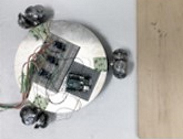
地震教育に用いるための高加速度を実現する全方向車両
地震動を再現するには,訓練用の起震車を用いて体験するか,加振機による正確な振動を用いて実験することが一般的ですが,その中間の手軽なものがこれまでありませんでした.ローラを用いた全方向車両に乗って体験するものがありますが,もう少し小型で一人でも搬送から準備までできるサイズでデモンストレーションができるものが必要ということで,全方向車両ながら強力な加速性能を得る方法を考えました.オムニホイルの場合,進行方向に対して車体側方の車輪が主に駆動力を発生しますが,慣性力によって荷重中心がずれてしまうと駆動力が伝えられず空転し,必要な加速度を得ることが困難なのです.そこで,車輪の配置を周方向から放射方向に変更し,進行方向の後ろ側の車輪を有効に活用する方式を検討しました.このままでは,ヨー方向(回転方向)を支持できず,動かしている間に方向が変わるので,捻じれ放射という配置にして,主に並進方向に駆動力を発生し,回転方向にも修正ができるように工夫しています.
オムニホイル外周の小車輪がちょうど爪のように路面に喰い込んで回るため,高トルクのモータと組み合わせ,高加速度を実現しました.仮に滑っても制御が有効に掛かっていれば振動動作を維持することができます. |
 |
掲載論文
加藤恵輔, 広瀬茂男, 吉田稔. "捻じれ放射配置オムニホイルによる全方向移動機構を用いた可搬型地震動シミュレータ-高加速度を実現する駆動機構-" 日本地震工学会論文集 19.7(2019), 56-66. |
全方向車両を用いた加振台を操作するための自己位置推定と操作誤差補正制御
全方向車両を遠隔操縦で動かすのは意外と難しく,まっすぐ前後に振動させているつもりでも,横に移動したり,中心から外れたりするなど意に反した挙動となります.車体のスリップも原因ですが,意図しない不正確な操作も原因となるため,これを修正するため,画像処理を用いた,自己位置推定,位置修正のための制御,操作意図認識などの機能を試みました.操作レバーを前後に振っているだけでも,操作が不正確であれば,だんだんとドリフトしていくことになるので,中心位置に戻す制御を加えながら操作することで,先の地震動を操作系で生成し,全方向車両を動かすことでデモンストレーションを行う方法について取り組みました.
小学生から一般の人まで参加する展示会に展示したこともあり,遊び感覚で実際に操作してもらいましたが,簡単に操作されていることからも有効性があるのではないかと考えています. |
 |
| 担当者 山路(2016年度 卒業) |
2020年度
ご存じSARS-CoV-2の問題があり,春学期は開始が延期となり,中盤はオンラインのみの活動により,構想検討と設計の一部,予備解析の一部程度しかできず,夏休み〜秋学期は,人数を制限した活動となり,冬からまた人数制限が厳格化するなど,多難な一年でしたが,その中でも以下のような実験機を何とか開発することができました.
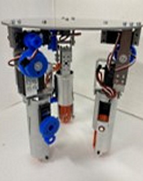
爬虫類型・哺乳類型に変形可能な4脚歩行ロボット
4脚ロボットの形態により移動性能・特性が変わります.爬虫類型は低い重心で安定しており,万一転倒しても胴体が路面に接触するだけで済みます.哺乳類型は足の長さを歩幅に反映できるため移動速度を上げられ,また,跨ぎ越えできる高さを大きくできるという特徴があります.脚は最低3関節あれば動作可能ですが,軸の方向が変わるため,これを切り替えるための機構を追加しています.このような機構構成を持った脚式ロボットは存在しないため,提案したというのが本研究です.
現在,本機体の後継機を開発中であり,2023年度に報告予定です. |
装置全体が完成したら公開します.
現在改良機開発中. |
| 担当者 別所(2021年度 修了) |
段差乗り上げを実現するオムニホイルおよび全方向車両
| すでに開発した新しいオムニホイルは乗り越え能力を上げることができたものの,構造が複雑であり,車輪の回転角によっては乗り上げ性能が変化するという問題がありました.乗り上げ性能を維持しながら,もっと簡潔なものができないかと検討し,リング状の小車輪を組み合わせ,捻じれ放射配置にした結果,車輪直径の1/2を実現し,通常のオムニホイルよりも高い段を乗り上げられます.また,有限個のリングが爪のように引っ掛かって乗り上げられるため,車輪直径の1/3を超える大きな段であっても乗り上がることが可能となりました. |
 |
| 担当者 斉藤(2021年度 修了) |
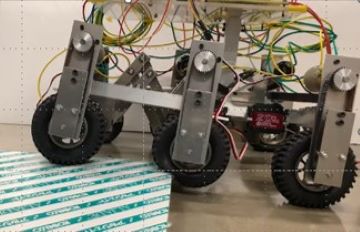
対地適応機能を有した4脚歩行ロボットに用いる足機構と凹凸への適応制御
| 4脚歩行ロボットの基本歩容を変えずに対地適応能力を向上するために,足部に設けられた4点の接地部に対し,対角を対として動作させ,凹凸に適応することを提案していますが,接地状態によって足裏機構が傾斜するため,胴体をまっすぐに保つための支持モーメントの特性に影響することがあります.胴体を動的に制御することに比して,さらに簡潔な制御ができないか検討し,足首2自由度のみをローカルに制御することを考えました.急峻な挙動も姿勢を崩す原因となるため,柔らかさを考慮した制御を行うため,機械的なインピーダンスを調整する制御を行っています. |
 |
| 担当者 傅(2020年度 修了) |
|
摘まみ上げ機能を実現する巻き取り機構と操り動作機能を有した4指ハンド
| これまでに,平ベルト型,有限回転角の並列丸ベルト,無限回転角の並列丸ベルトと改良を進めてきましたが,それぞれに課題がありました.小さいものを把持するのが不得意,摘まみ上げ機能に限度がある,摘まみ上げる際に対象物の姿勢が変化するなどの問題を抱えていたため,これらを解決すべく改良機を開発しました.基本構想は共通ですが,ベルトの等速性を得るための機構構成に変更しています.改善を繰り返してきた機体ですが, |
 |
| 担当者 泉澤(2020年度 修了) |
|
対地適応機能を向上するリンク機構および連結機構を有した車輪型連接ロボット
| 車輛を複数連結することで,相互に押す,引くことができ,荒れ地の移動性能を上げられると考えています.しかしながら,単に連結するだけでは,姿勢が崩れ,駆動力が有効に伝達しなくなってしまいます.駆動力の作用点に着目し,これを必要な場所に移すことで,姿勢を崩さず,有効な駆動力伝達の実現を目指します.また,凹凸に適応するための機構も同様で,作用点となる部分を調整することで,円滑な適応動作が可能となります. |
 |
| 担当者 藤野(2019年度 修了) |
|
2021年度
2021年度はSARS-CoV-2の影響もあり,試作を特徴とする研究室としては,影響が甚大かと思っていたのですが,思いの外,試作,実験を行うことができました.
4足歩行ロボットと対地適応性の向上を目指した足先機構に関する設計と制御
4足歩行ロボットの歴史は長く,昨今ではホッピング主体の完成度の高いロボットも開発されています.転んでも自力で起き上がる機能すらある魅力的なロボットですが,ここは少々趣向を変え,ゆっくり確実な動作とされる,静歩行,準動歩行を主体とした移動に着目しました.屋内や人間の傍で活動する場合,安全を期すればいつでも停止できる,あるいは見るからに安定していそうな動作であることが重要と考えています.開発したロボットの特徴は,狭隘な場所での移動性を考えて脚は哺乳類型に配置していることと,トロット歩容のような対角足の接地でもある程度の支持モーメントを生成できるような足機構を備えていることです.
用語
2脚ロボットと4足歩行ロボットでは若干定義が異なります.4足歩行ロボットについて説明します.
静歩行:支持多角形(接地している足で構成される多角形)内に重心,CP(荷物重中心),ZMP(Zero
Moment Point)が存在し,ある瞬間に動作を止めてもロボットは転倒しない状態となることが特徴です.
準動歩行:歩行サイクル(歩容と呼ばれる)の中で静歩行の時間と動歩行の時間が混在するような移動.対角の2脚を交互に接地する,あるいは駱駝のように左右2脚を組とした歩行の場合,足裏が小さければ,動的なバランスを取らないと転倒します.
動歩行:接地した足の移動面からの反力と機体の慣性力が釣り合っていることで,転倒しない状態を継続できる状態です.走行のように1足も接地していない状態がある場合,次の接地時にバランスを取ることができる状態で移動を継続できます.ある瞬間に動作を止めればロボットは転倒するので,止まる際にも,遷移していくような動作制御が求められます. |
 |
| 担当者 傅(2020年度 修了) |
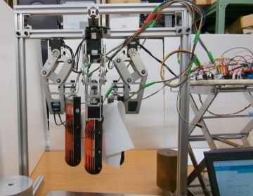
摘まみ上げ機能を実現する巻き取り機構と操り動作機能を有した4指ハンドの改良した3指ハンド
ロボットハンドの研究は現在も盛んに行われており,人間の手のような構造のものと全く異なる動作原理によるものがあります.対象物の摘まみ上げ,把持には指の構造が確かに有効であるが,対象物の形状や柔らかさなどを的確に理解しなければならず,高度な認識と制御を必要とします.特に摘まみ上げ動作を簡潔にできないか考えた結果,指にベルト状の機構要素を配置することで,タオルのような柔らかいもの,紙のような薄いものに対して有効であろうと考えました.ベルト部形状に関しては,以下のような変更を繰り返してきました.
- 2指の対向する平ベルト,指の根元の回転支持により開閉.
- 3指の球面配置の丸ベルト(有限動作範囲,各指回転可能),指の根元の回転支持により開閉.
- 3指の球面配置の丸ベルト(無限回転),指の根元の回転支持により開閉.
- 3指の球面配置の丸ベルト(無限回転,周速等速化,各指回転可能),開閉動作は平行リンク機構により並進的な動作.
3指であっても各指が回転できるため,ある程度対向したのと同様な状態にできるため,紙を摘まみ上げることも可能でした.また,開閉動作を並進としたため,ベルトで摘まみ上げることができれば,指の開閉を行わなくても把持に移行することが可能となることが特徴です.
|
 |
| 担当者 泉澤(2020年度 修了) |
夜光雲観測のためのカメラ雲台ジンバル機構の設計と制御,観測気球係留索巻き取り装置の開発
夜光雲は高緯度の高層に発生する氷の粒にて光が拡散する現象で,通年観測されるものではなく,春・秋に観測され易いとされています.近年,中緯度帯でも観測されるようになってきており,日本でも北海道北部でも観測できるようになってきています.
観測されるようになってきたのか,元々観測されるものが観測できていなかったのか,によってこの現象の解釈が大きく変わります.北海道が梅雨のために観測しにくかったのではないかという仮説を解明するため,低層雲より高高度で撮影できる手段を開発することがこの研究の発端です.ラジオゾンデに使われるようなヘリウムガス気球にカメラを懸垂させる構造となっており,これを係留索につなぎます.
夜間に風の影響を受けないようカメラを常に特定の方向に向けて安定化させるための制御を行うことと,係留索に過剰な負担が掛からないよう制御を行うことが,この研究での技術的な課題です. |
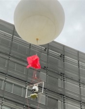 |
| 担当者 別所(2021年度 修了),守谷(2020年度 卒業) |
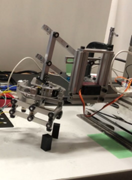
歩行時の下肢動作軌道の解析とこれを実現するための装置の検討
| 人間の下肢の動作は思いの外,複雑でありロボットのような規則的な軌道とはかなり異なるものです.機械によって反復的な動作を人間に加える場合,単純な機構では関節や筋肉に負担を掛けることとなってしまいます.そこで,制御を掛けて,複雑な軌道を再現できることが求められる上,強力であること,ある程度の可逆駆動性を有していることなど考慮すべき点があります.しかも地面に当たっているのと同様な感触とするには,可逆駆動性は少ない方が良いなども難しい点です.そこで,上下方向にはモータの角度次第で正弦波状の変位を生成する機構を利用し,接地時には可逆駆動性を減少させ,遊脚時には可逆駆動性を大きく利用できる特性の減速機を利用します. |
 |
| 担当者 伊藤(2021年度 修了) |
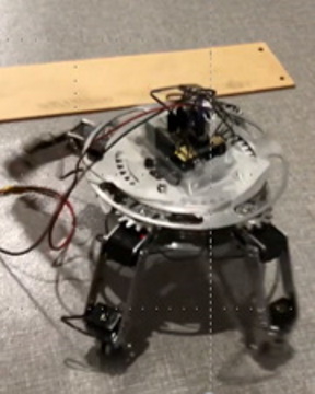
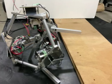
段差乗り越えを目指した転動動作を行う放射配置された4足歩行機械
| 脚式ロボット新たな構成法を検討したいというが本研究の発端です.脚は不整地移動に適していて,脚は転倒することも往々にして起こり得ます.高度な制御によって転倒しない,あるいは起き上がる制御機能を用いるのも有効で真っ当な考え方ですが,これに対して,転んでいる状態がない,もしくは転びながら移動するという移動形態を実現すると球状の機体にあるのではないかと考えてみました.常に転がっているのは非効率かつ経路が不安定になるので,正四面体の頂点にオムニホイルを取り付けて全方向車輛として平地移動を行い,段差にて脚が出てきて乗り上げるような動作を行うという形態のロボットを開発しました.試作機で車輪はありませんが,確かに段差を転動して乗り上げることができました. |
 |
| 担当者 速水(2020年度 卒業) |
2022年度
2022年度もSARS-CoV-2の影響もあり,試作を特徴とする研究室としては,2021年度同様に試作,実験を行うことができ,ほぼ通常の活動ができるようになりました.
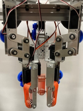
摘まみ上げ機能を実現する巻き取り機構と操り動作機能を有した4指ハンドの改良した3指ハンドをさらに改良した4指ハンド
ロボットハンドの研究は常に盛んに行われており,人間の手のような構造のものと全く異なる動作原理によるものがあります.対象物の摘まみ上げ,把持には指の構造が確かに有効となるが,対象物の形状や柔らかさなどを的確に理解しなければならず,画像認識など高度な認識と制御を必要とします.特に摘まみ上げ動作を簡潔にできないか考えた結果,指にベルト状の機構要素を配置することで,タオルのような柔らかいもの,紙のような薄いものに対して有効であろうと考えました.ベルト部形状に関しては,以下のような変更を繰り返してきました.
- 2指の対向する平ベルト,指の根元の回転支持により開閉.
- 3指の球面配置の丸ベルト(有限動作範囲,各指回転可能),指の根元の回転支持により開閉.
- 3指の球面配置の丸ベルト(無限回転),指の根元の回転支持により開閉.
- 3指の球面配置の丸ベルト(無限回転,周速等速化,各指回転可能),開閉動作は平行リンク機構により並進的な動作.
- 4指の球面配置の丸ベルト(無限回転,周速等速化,各指回転可能,ベルト配置改善,ベルト張力適正化),開閉動作は平行リンク機構により並進的な動作.平行リンク機構の初期姿勢変更
4指であれば,確実に指が対向し,接触力ベクトルを同一線上に配置できるため,紙を摘まみ上げることも可能でした.また,開閉動作を並進としたため,ベルトで摘まみ上げることができれば,指の開閉を行わなくても把持に移行することが可能となることが特徴です.さらに,指の側面でも把持できるようにしたため,操り動作の安定性が向上しました. |
 |
| 担当者 渡辺(2021年度 修了) |
段差乗り上げを実現する捻れ放射配置型小車輪を有するオムニホイル型車輪機構
全方向移動車輛を構成するのに一般的となったオムニホイルですが,扱いの手軽さとは裏腹に段差を乗り越えにくいという弱点があります.周方向に配置された樽型の受動小車輪の直径が小さいことが原因です.これを大きくするにも限度があり,3つ並べるのが限度であるため,車輪直径に対して大きくても1/3程度までとなります.そこで,この車輪を大きくするための配置を検討した結果,小車輪を互いに入り込むような捻れ放射配置にすることで直径を1/2以上にすることができました.段に差し掛かった際,この車輪が掛かるように回転角を制御すれば車輪直径の1/4くらいは乗り上げられるようになっています.
設計,加工を簡素化することを狙いとしていましたが,多角形接地となる問題があることから,さらに内側に通常のオムニホイルを配置し,平地はこれを用いて円滑な動作を行い,段差に差し掛かったら上記の捻れ配置小車輪を持ったオムニホイルを段差乗り上げに活用しています. |
 |
| 担当者 斉藤(2021年度 修了) |
輝点検出を画像処理により行うマルチコプタの離発着動作に恭順する動作制御
マルチコプタは自在な運動ができ,環境認識性能次第で狭隘な空間にも進入できる利点があるものの,離発着には水平であることが求められます.また,実用,商用稼働のためには人間との距離を確保しておくこと望ましく,マルチコプタから受け取った荷物を移動型ロボットが運ぶことが現実的と考えています.マルチコプタが離発着しやすくできるよう,移動ロボット側でもこれに恭順できる機能を実現しようと考え,マルチコプタとの相対位置関係を認識できるような画像処理系を実装しました.
簡潔なシステムを目指し,カメラは単眼としており,マルチコプタの被認識性を向上する為,輝点を用いたマーカを搭載しています.
基本原理を検証するため,全方向移動ロボットを用いていますが,他の形式を用いた方法も模索していく予定です. |
 |
| 担当者 岡本(2020年度 修了),近藤(2018年度 修了) |
段差乗り上げを実現する前輪跳ね上げ機構を有するオムニホイル型移動ロボット
全方向移動車輛の構成に一般的なオムニホイルですが,段差を乗り越えにくいという弱点があります.周方向に配置された樽型の受動小車輪の直径が小さいことが原因で,これを大きくするにも限度があり,3つ並べるのが限度であるため,車輪直径に対して大きくても1/3程度までとなります.そこで,段差に侵入する前輪を跳ね上げて乗り上げる方式を検討し,能動自由度を付与した結果,車輪直径の1/4くらいは乗り上げられるようになっています.
比較的,設計を簡素化できることを狙いとしていましたが,簡潔な機体構成の割に乗り上げ性能を確保できたと考えています. |
 |
| 担当者 増田(2021年度 卒業 2023年度 修了) |
ドアノブを把持可能なハンド機構
| 屋内を自在に移動するロボットにとって,ドアは難所のひとつです.建物自体をインテリジェント・ビル化して,ドアを自動開閉できるようにするなど,ロボットと連携できるようにする方法もありますが,既存の建物の場合,対応する改造等が難しい場合もあります.そこで,ドアノブを把持できるようなハンド機構を考案し,握って捻る動作ができる機構を開発しました.回転軸とドアノブ中心が若干合っていなくても適応できるような機構要素を入れるような工夫を施し,玉座型,レバー型のドアノブで実験を行いました. |
 |
| 担当者 川島(2021年度 卒業 2023年度 修了) |
4足と2足2腕モードを切り替える移動・作業ロボット
4足歩行ロボットの研究の歴史は長く,多様な試みがなされてきました.対地適応性の高さ,足を手としても利用できる特性が着目されており,運搬作業を行うための機体形態を検討しました.荷物を運ぶ際,車輪型の移動機構からの積み降ろし作業が必要となるため,この作業に求められる機能を検討するための機体開発を行いました.低地から一定の高さに対象物を移動させられることを目指した機体となっており,形状的な特徴,設計からの特徴は次のようなものがあります.
- 前後を異構造とした機体で,前足を段に近付け,後足を荷物の把持,持ち上げ動作に利用します.
- 前足は段にできる限り近付けられるような配置とし,足裏を大きくしておき,確実な支持モーメントを得られるようにします.
- 後足は荷物を把持し,体幹を逆立ちのように立てて,高所に荷物を移動します.
- 胴体には捻れおよびピッチの自由度を有しており,後足で対象物を把持し,体幹を捻って段の上に対象物をおくような動作を行います.
4の機構は2自由度であるが,大きなトルクが働くところであるため,干渉駆動構成としてモータ動力を有効に利用できるように工夫している. |
 |
| 担当者 高橋(2021年度 卒業 2023年度 修了) |
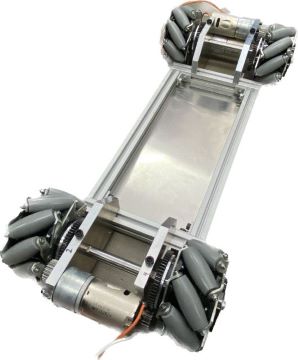
ピッチ軸,ロール軸の2軸で適応可能な交叉リンク機構を有した装輪型移動ロボット
斜面に装輪型移動ロボットを安定させて移動するには,可能な限り,動的なバランスを必要としない低速な移動が適していると考え,また,慣性力に頼らない移動には低出力のモータによる移動となるため,斜面を最大傾斜線方向だけでなく,等高線方向にも移動できる必要があると考えました.従って,2軸で適応できる必要があり,しかも重心が斜面の谷側に移動しないよう工夫しなければならないため,交叉平行リンクを用いました.これにより,ピッチ軸,ロール軸の回転中心を地表面に合わせることができるため,安定余裕が著しく減少する問題が回避できると考えています.
マルチコプタとの協調作業にも適している形態の移動ロボットと考えております. |
 |
| 担当者 岡本(2020年度 修了) |
ピッチ軸を地表面まで下げた6輪型移動ロボット
| 惑星探査車輛など軽量で優れた対地適応機能を有した移動ロボットには,ロッカー・ボギー機構が用いられます.前後2輪を梁で結んだボギー機構に対し,さらに1輪を梁で結んだロッカー機構で構成され,これを左右に配置した車体となっています.さらに特性改善ができないかと考え,特に前輪が移動面の凸地形,特に段差に差し掛かったときに車輪ごと後ろに押し戻される挙動となるので,これを解決するために,交叉配置平行リンクを用いることとしました.車軸よりも低い位置にピッチ軸回転中心が配置されるため,段に差し掛かって前輪が押し戻されると,ボギー機構を介して前輪が上がる方向に動作するため,より容易に乗り上げられるようになることを期待した機構です. |
 |
| 担当者 泰(2021年度 卒業 2023年度 修了) |
2023年度
2022年度,まだまだ制限のある中で尽力した学生も数多く,前半から学会にて報告致しました.
1モータで脚ロボットの足先軌道を生成するリンク機構
多脚ロボットは,自在な移動性能を持ち,段差など不連続面でも移動できる反面,制御には一定の技術水準が要求され,必ずしも簡便な利用ができるとも言い難い面があります.機構の工夫で足を上げながら前進する軌道を生成できないか検討し,4節リンク機構を組み合わせたものを発案しました.足先機構を生成する機構はチェビシェフリンク機構やテオヤンセンの機構が有名ですが,接地時には足先高さが下がっているため,遊脚が前に出たときそのまま下ろせる機構を検討しています.原理の検証機として前2足のみ試作し,後ろは車輪で構成された試作機を開発し実験を行いました.
原理検証のための機体でしたが,一定の段差を認識なし,制御なしで乗り上げることができ,本研究のコンセプト通りの動作が実現できました. |
 |
| 担当者 吉澤(2022年度 卒業) |
球面リンク機構・交叉配置平行リンク機構を用いた連結型装輪ロボット
連結型の移動ロボットは,脚,車輪,クローラとも優れた移動性能が期待できます.移動面の状態によっては,後ろの移動ユニットから押された前側のユニットが移動面に引っ掛かって姿勢が崩れることも起こります.この原因を考えたところ,連結機構の高さ,即ち作用点の高さではないかと考えました.連結機構を下げてしまうと移動面との間隔が少なくなるので,連結機構を下げたかのように機能する機構がないかを考え,球面リンク機構の利用を検討しました.これにより,機構の高さを保ったまま,作用点を任意の高さまで下げることができ,車輪の接地点まで下げれば,後ろの車体は前の車体の姿勢を崩すことなく力を伝えられます.
細かな凹凸についても,各車体ユニットにある4輪の動作が重要と考え,前輪が段差や突起に対して上がりやすくなるよう前後輪を結ぶリンク機構の回転中心高さを下げる必要があると考え,交叉配置された平行リンクを用いて回転中心を調整し,滑らかに段差乗り上げできるような機構を実現しています. |
 |
| 担当者 伊藤(2022年度 修了) |
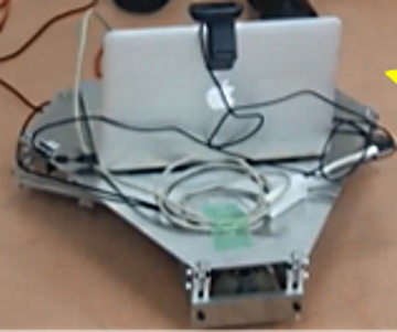
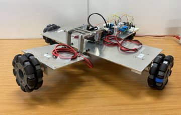
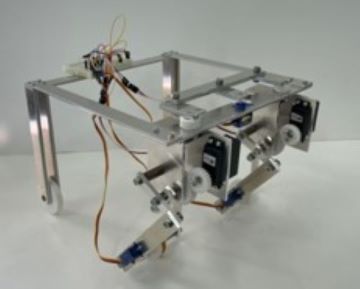
全方向移動型ロボットを用いたリハビリテーションを行う装置
脳卒中など麻痺に繋がる危険のある手術後は,できるだけ早くリハビリテーションを行う必要があると言われています.麻痺からの回復と拘縮とよばれる筋肉や関節が固まることを避けることが目標となります.畳2〜3畳の大型で高度な機能の装置が開発される一方,現場では簡潔な器具が利用されています.理学療法士,作業療法士の方々の負担が大きく,また,患者本人のモチベーションを維持する必要など,多くの課題があります.現場で利用できる比較的簡潔な装置を目指しながら,自動化,あるいはアシストなど理学療法士,作業療法士の方々がより患者本人の精神的な支援と動機の維持に携われるような装置の開発に取り組んでいます.
脚軌道は思いの外複雑であるため,自在に動くことができるよう,全方向車輪を利用しました.車軸を揃えて装置の幅を抑えるるため,メカナムホイールを用いた低床の装置を設計しています. |
 |
| 担当者 山田(2022年度 卒業 2024年度 修了) |
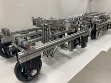
斜面に適応し沈み込みを抑制する多輪配置型装輪移動ロボット
クローラは建設機械や農業機械に用いられ,優れた対地適応性があります.乾いた土,砂,礫など崩れやすい移動面ではクローラの利用が効果的です.しかしながら,クローラは履帯とスプロケットの間に異物が挟まることもあり,製品も限定的で任意のものを利用するには費用を含め制約があるのも実情です.そこで本研究では,複数車輪列を並べることを検討し,斜面角度に合わせて広く接地することと,沈み込みに対して複数の車輪で支持して,駆動力と支持力を確保することを目指した機構を発案しました.
車輪はすべて同速度で連動し,各車輪とも操舵でき,ピッチ方向に適応できるような構造となっています.砂利を積み上げた安息角(32°)の坂を安定して走行しています.
駆動のパワーと慣性力に依存して駆け登るような走行ではなく,低速で確実な接地を維持したままの走行・挙動が特徴です |
 |
| 担当者 吉村(2022年度 修了) |
脚・車輪変形移動ロボット
歩行ロボットを議論する際,エネルギ効率が話題に上ります.機体の支持と移動のための駆動にアクチュエータを用いるため,平地の一定速度の移動でも余計にエネルギ消費が発生します.脚・車輪ハイブリッド移動ロボットが発案されており,脚に駆動された車輪を持つもの,受動車輪を持ち脚動作で推進力を生成するものなどが研究されています.脚移動は,複雑な地形,幅の狭い通路などで利用すると設定し,それ以外は車輪で移動するという運用法がエネルギ効率の面で有効であると考えました.
車輪で移動する際は,脚がエネルギ消費をしないようにするため,折り畳まれた膝や足首は突起と穴によって,関節駆動をしなくても姿勢を維持できるような機構を組み込んでいます.
車輪機構は,2のモータによる差動駆動となっており,歩行時は重量の影響を低減するため,跳ね上げて体幹に近付け,重心を高く保って固有振動数を下げるような配置としています. |
 |
| 担当者 南(2022年度 卒業) |
西之島の鳥類・節足動物観察のためのローバの開発
| 2023年9月の調査に向けて短期集中で取り組みました.プロジェクトをご覧下さい. |
|
| 担当者 高橋,猪股,研究室有志 |
2024
As the 2023 academic year continues, the
influence and restrictions of SARS-COV-2
have disappeared, and it is as if the mist,
fog, and haze have cleared. Many students
were highly motivated and were able to produce
results. Even students who did not originally
have a background in mechatronics-related
crafts worked carefully to turn their ideas
into something tangible and create mathematical
models for that purpose.
Robot consisting of hands, arms and an omnidirectional
mechanism that opens and closes doors
| There is a term called "robot-friendly,"
and there are ideas for adding devices and
functions to buildings to make it easier
for robots to act, and for them to cooperate
and collaborate with robots. The idea of
??eliminating barriers to movement itself,
such as barrier-free access, is also widespread,
but the framework of a building has a lifespan
of several decades or more, and although
interior work is possible once it is constructed,
it is not easy because it incurs a lot of
costs. Therefore, we devised a way to make
the robot mobile and usable within existing
building facilities. The hand can handle
both ball-shaped knobs and lever-shaped knobs,
and has a mechanism that allows it to grasp
them just by opening and closing them. This
robot is composed of a hand that does not
require high positioning accuracy, a lightweight
arm, an omnidirectional body that can move
over small steps, and fenders that cover
the wheels and can receive doors without
damaging them. In an omniwheel omnidirectional
vehicle, if a cycloidal trajectory is used,
it can ride up steps, but this is expanded
further to hook the door with the fender
and support it while passing through. Some
people may find the idea of ??a human getting
their foot caught in a door unpleasant, but
the idea behind this is that if the soft
part of the casing that is not in contact
with the moving surface hits the door, it
probably won't be a bother. |
.jpg) |
| 担当者 高橋(2023年度 修了) 川島(2023年度 修了) |
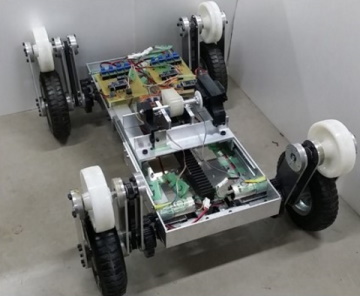
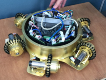
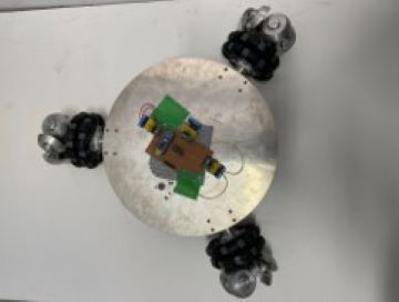
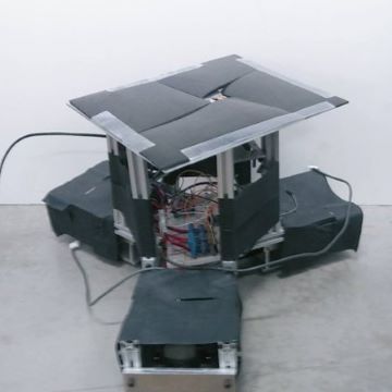
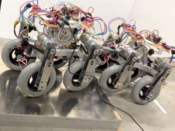
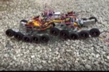
Mobile robot with 4-Mecanum wheel + 1-Omniwheel
| Mobile robots that can move freely by translating
along the X- and Y-axes and rotating along
the yaw axis are particularly suited to moving
in narrow spaces, but both omni-wheels and
mecanum wheels have a small diameter for
their barrel-shaped rollers, making them
generally poor at climbing over steps. Previous
research has attempted to use nine omni-wheels
to adapt to steps, and this was devised with
the idea of ??making this even simpler.In
response to this, the mechanism is based
on four mecanum wheels with one additional
omni wheel.With both mecanum and omni-wheels,
if all the wheels are not on the ground,
the free wheels will spin and the robot will
not be able to move as intended, so a rocker-bogie
mechanism is configured, with two mecanum
wheels and one omni wheel arranged in a triangle
on the bogie, and two mecanum wheels are
placed on the rocker, but with a degree of
freedom in the roll direction, they can twist
and respond to the bogie mechanism, allowing
all wheels to touch the ground. When the
two front wheels come into contact with a
step, the driving force of the remaining
three wheels pushes them up, and as the central
omniwheel is in contact with the ground in
the driving direction, the small wheel actually
catches the step and climbs, and the remaining
two wheels act as if they are pulled up by
the three wheels that have climbed up the
step. |
 |
| 担当者 増田(2023年度 修了) |
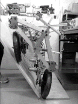
Mobile robot with a lowered center of rotation
for the rocker-bogie mechanism
| It started with the idea that the climbing
performance would change depending on the
height of the end of the cantilever to which
the wheel is attached, and that lowering
this would make it easier to climb up. If
the pitch axis height of the bogie mechanism
is high, when the front wheel approaches
a step, it is pushed backwards and gets caught,
so the idea was that by lowering this, the
front wheel would be able to rise up more
easily and climb up the step more easily.
In the case of a rocker bogie mechanism,
if the rotation axis is lowered, the mechanism
becomes closer to the moving surface and
is more likely to interfere, so the center
of rotation needs to be moved outside the
mechanism structure. To achieve this, two
sets of parallel link mechanisms can be installed
so that they cross, and it is even possible
to make the center of rotation coincide with
the moving surface. This was applied to both
the rocker mechanism and the bogie mechanism,
and placed on the left and right, to develop
a vehicle in which the rocker mechanisms
move differentially. All six wheels can be
steered and are driven individually. A vehicle
was developed using the proposed method,
and experiments were conducted, and it was
noted that it was able to climb up smoothly
in particular. The front wheels are easier
to climb up because the load on them is lighter
when climbing up. The middle and rear wheels
bear a greater load, but once the front and
middle wheels climb up, they will pull the
rear wheels up and press them against the
wall of the step, making it possible to climb
up. |
 |
| 担当者 泰(2023年度 修了) |
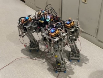
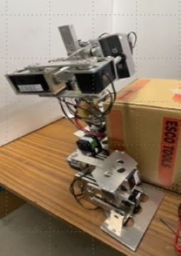
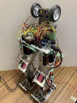
Humanoid upper limbs with linked trunk tilting
freedom
5-degree-of-freedom neck joint mechanism
for humanoids
The history of research and development of
humanoids is long, and many excellent robots
have been developed. It is difficult to find
the significance of developing a humanoid
in this situation, but we are developing
this robot out of a desire to try developing
a robot that is different from conventional
robots. What has been developed is the head,
fixed neck, torso, arms, and pelvis, with
the hands, legs, and feet still to come.
A distinctive feature is the rod that connects
the shoulders to the pelvis, giving it a
simple parallel link structure. When the
torso is tilted in the roll direction, the
shoulders also drop, but the design has been
adjusted so that they move in the upright
direction. This is a configuration of degrees
of freedom that is the result of considering
natural movement with a small number of degrees
of freedom. The arms have motors placed around
the shoulders, giving them four degrees of
freedom. In order to prevent interference
with the surrounding environment and to allow
for the installation of any cover, the arms
are structured as frame only as much as possible.
We believe that the freedom of the neck is
important when using a humanoid for interaction
with humans, and when using a camera attached
to the face to recognize the surroundings
and recognize humans who are conversing with
it. In particular, when the trunk is thicker
than the head, it becomes necessary to look
down with the camera. We thought that when
conversing with humans, it would be possible
to create a certain degree of line of sight
with the movement of the neck, so we developed
a neck mechanism with sufficient freedom
of movement. We replaced the neck of an already
developed humanoid with a Stewart Platform
type neck. <BR>When viewing the human
head as a sphere, the center of rotation
is never the center of the head, but is at
the rear, so the surface of the face moves
a lot. However, it is certain that from a
mechanical standpoint, supporting it at the
center reduces the power consumption of the
motor, and so we used the proposed mechanism
to achieve human-like movements. |
.jpg) |
担当者 吉田(2021年度 修了)
担当者 河西(2023年度 修了) |
西之島の鳥類・節足動物観察のためのローバの開発
| 2024年9月の調査に向けて短期集中で取り組みました.プロジェクトをご覧下さい. |
|
| 担当者 中村,山田,研究室有志 |
2025年度
2023年度から続き,意欲的に取り組む学生が多かったので成果として出していくことができました.研究の方針が見えてくると,火が付いたかのように前進する学生が多く,限られた期間ながらも各自が成果を散らかすかのように出していったような年度だったと思います.
(公表され次第,記載します.)
(公表され次第,記載します.)
(公表され次第,記載します.)
(公表され次第,記載します.)
可変式重力補償機構
|
|
担当者 篠本(2016年度 修了)
担当者 李(2024年度 修了) |
以上は2025年3月での研究紹介ですが,論文掲載,学会にて報告次第,新たに追記していきます.
名前を掲載している研究は,学会発表,特許公開済みのものですが,それ以外にも学生の尽力の成果を出していく準備中のものもあります.